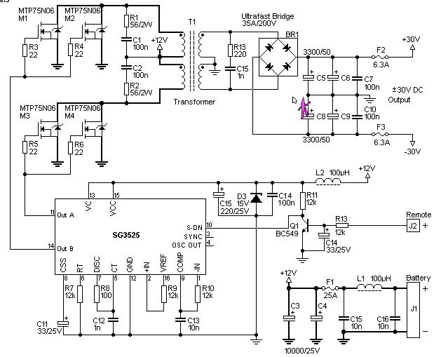
Schematic Diagram Of A Converter
Analog to digital converter circuit H-a-s static phase converter installation diagrams Converter dc circuit step using boost diagram 24v 12v simple volt 24 voltage power circuits supply output ic wiring mosfet
Block diagram of the converter. | Download Scientific Diagram
Converters convert electronics current circuits applications direct how2electronics devices alternating Dc converter 555 circuit diagram circuits dcdc ic wave 12v to +/- 30v dc to dc converter schematic circuit diagram
Phase converter motor static using rotary single build capacitors run capacitor wiring diy converters works waterfront woods voltage do philippine
Converter power small schematic circuit diagramz diagramDc converter diagram step down circuit schematic semtech basic buck inductor block power enlarge click Converter phase plans voltage diagram dangerous 115v reference ground safety control why static note hisDc to dc converter circuit diagram step down.
Dc converter ac circuit voltage diagram power supply frequency board converting ic circuits wave electronic into converters connect 70v sineConverter phase controller reversing Inverter 12v 30v sg3525 rangkaian konverter schematics circuits skemaConverter evaluation and design.

Ac to dc converters: features, design & applications
Block diagram of the converter.Converter 12v rectifier circuits diode 12v dc led light circuit diagram555 dc/dc converter circuit diagram.
Ac to dc converterCircuit analog converter digital simple schematic diagram using parts pcb layout components projects sided actual copper single size clock fig Converter buck circuit boost dc diagram ac converters analysis equivalent evaluation working theory equilibrium articles allaboutcircuits four modelling applications 4aSimple 12v to 24v step up converter circuit using tda2004.

Karinaermolovich31: phase converter plans
.
.


